

Reduce paper background noise
Reduce paper background shading, uneven lighting, and document discoloration to help separate drawing linework before vector tracing.
Turn floor plan images, field sketches, and technical drawings into 2D vector outlines. Export DXF and SVG files to continue drafting in CAD.
Capabilities
Four capabilities to prepare drawing images for further drafting in CAD.
Reduce paper background shading, uneven lighting, and document discoloration to help separate drawing linework before vector tracing.
Convert raster linework into independent vector paths that drafters can inspect, snap to, trim, and adjust in CAD.
Download standard DXF and SVG files ready to open in CAD and graphics software without proprietary format lock-in.
Keep the original raster image side by side as a reference to check wall alignments, critical dimension values, and handwritten notes.
How It Works
Start with your drawing image and follow these steps to export CAD vector outlines.
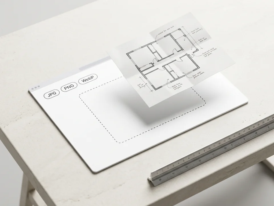
Choose a JPG, PNG, or WebP drawing image with high contrast and legible lines, such as a floor plan, field sketch, or technical drawing.
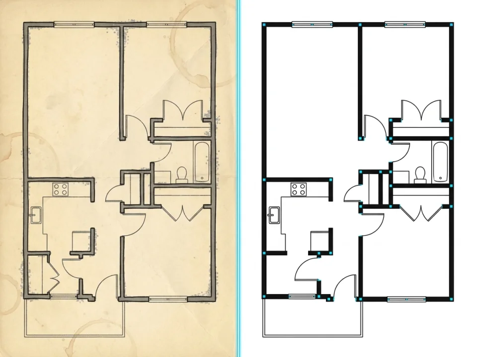
Review the credit cost, run AI cleanup to reduce background noise, and generate vector outlines directly in your browser.
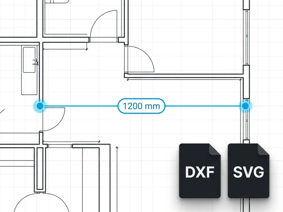
Optionally click two points on a known dimension to set real-world units (mm, cm, or m) in your browser, then download DXF or SVG files, verify details against the original, and continue drafting in CAD.
Drawing and linework illustrations
Compare building photos, floor plans and hand-drawn sketches with their linework references.
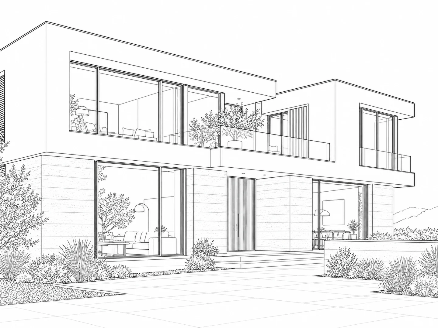
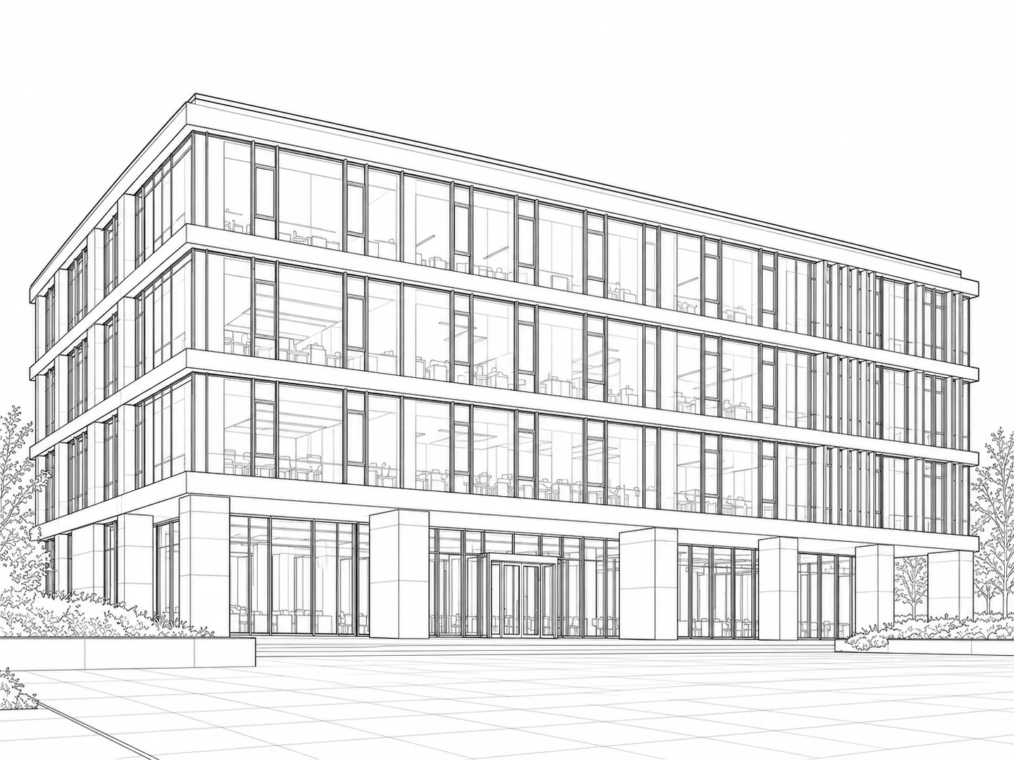
Building Photography
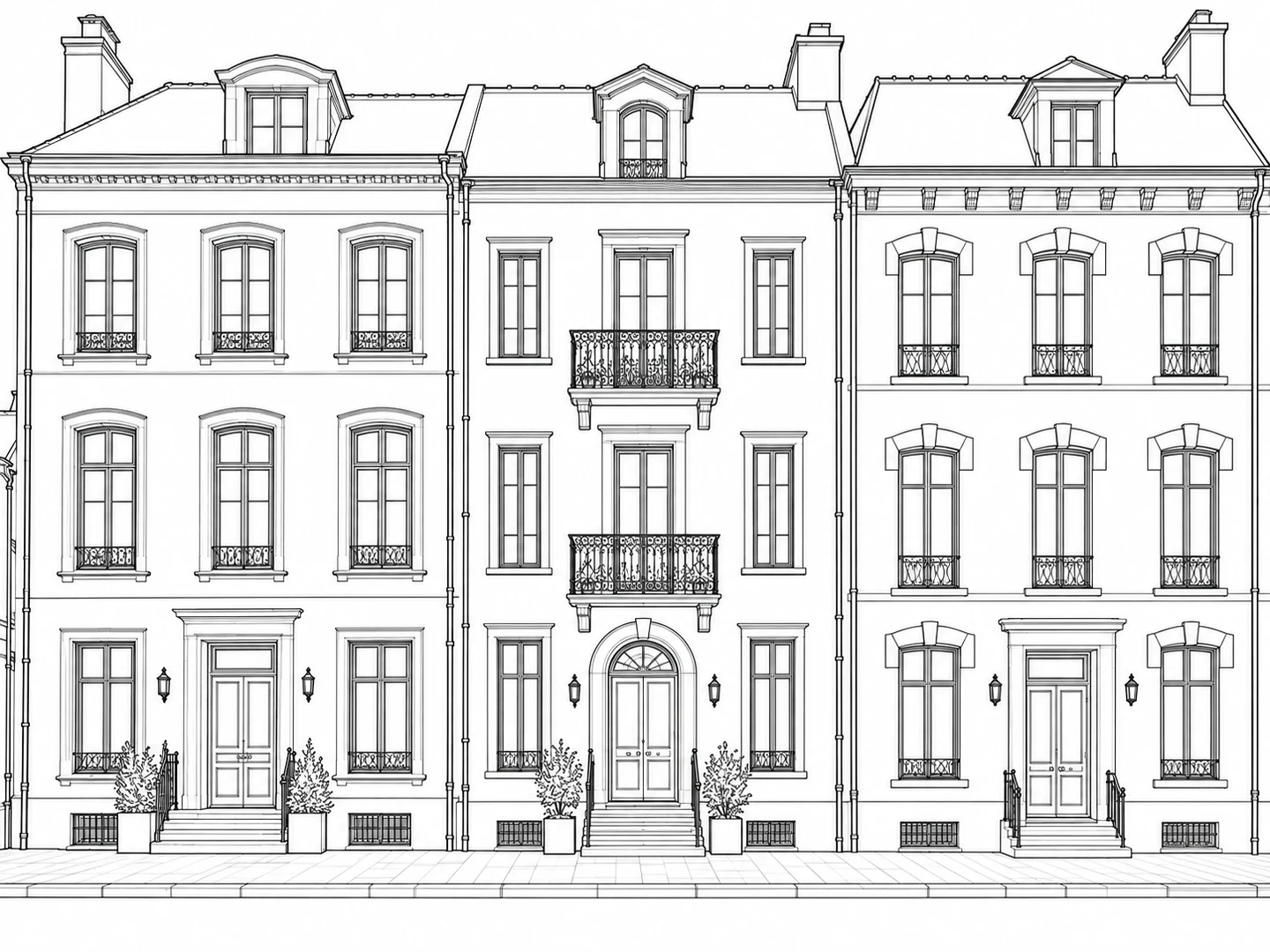
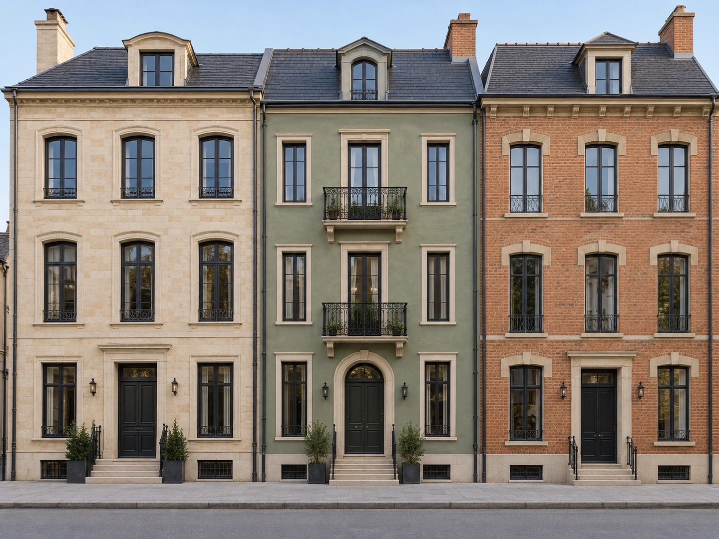
Compare a building photograph with its line drawing to see windows, stairs and facade outlines in two dimensions, as a reference for architectural drafting in CAD.
Photo perspective affects proportions. Verify site measurements and correct scale before survey or construction use.
Architectural Layouts
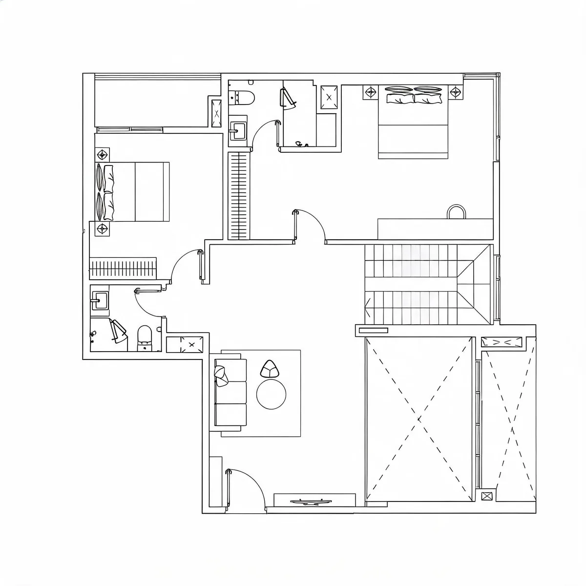
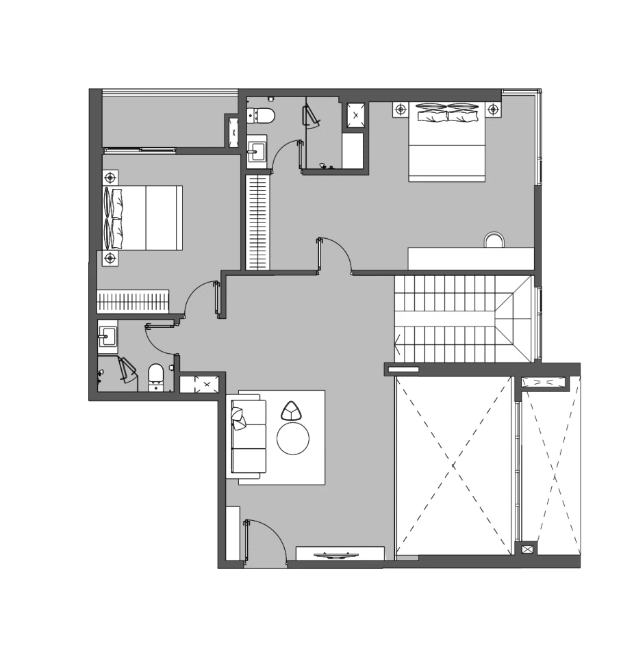
When a renovation starts with a floor plan image instead of a CAD file, vector outlines give you a base for the next drawing. Trace the visible linework, then check and adjust the outlines in CAD before drawing new partitions or arranging furniture.
Measure room depths on site and verify door swing directions against actual field conditions before finalizing drawings.
Field Measurement
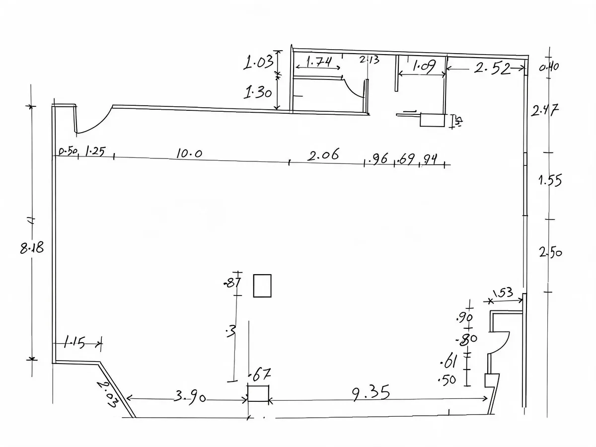
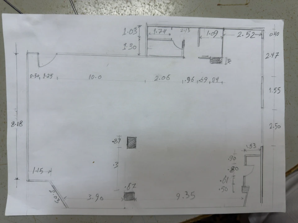
Surveyors and contractors frequently record pencil notes and rough dimension sketches on clipboards. ImgToCAD extracts sketched pencil strokes into vector lines, providing rough layout outlines that can be adjusted in CAD.
Compare all dimensions against original handwritten field notes and manually create verified dimension objects in CAD.
Workflow Comparison
A side-by-side look at the practical differences across common drawing workflows.
| Comparison Factor | Attach image as underlay | Redraw manually from scratch | ImgToCAD workflow |
|---|---|---|---|
| Starting output | Static raster image placed in CAD model space | Blank CAD workspace with reference drawing | Editable 2D vector linework paths (DXF / SVG) |
| Paper background & noise | Paper texture, stains, and scan shadows remain | The drafter visually interprets and filters paper marks | AI cleanup reduces background shading and isolated spots |
| Editable CAD elements | None; pixels cannot be snapped, trimmed, or edited | Lines, arcs, layers, and blocks drafted manually | Vector outlines ready to inspect, snap, and trim in CAD |
| Scaling & quality control | Image scaled and positioned manually; no geometry | The drafter controls scale, tolerances, and layers throughout | User scales vector paths to known dimensions; checks details |
| Best suited for | Visual reference where no vector edits are needed | High-precision parts, complex engineering, or structural modeling | Vector drafting starting point from clear plans, sketches, and scans |
ImgToCAD provides 2D vector path outlines as a drafting starting point for clear architectural plans, field sketches, and legacy technical drawings. It does not automatically recognize structural objects or produce constrained parametric models. All critical dimensions and load-bearing details require independent professional verification before construction or manufacturing.
Verification Guide
Vector outlines provide a drafting starting point, while engineering accuracy remains human responsibility.
AI background cleanup may misread or alter numbers, and vector tracing may drop faint lines. Keep the original drawing open to inspect critical notes and dimension callouts.
Click two points on a known wall or scale bar in the converter workbench to set real-world units (mm, cm, or m) before downloading DXF, or scale the uncalibrated drawing in CAD.
Before converted linework is used for construction bids, permits, or parts fabrication, verified dimensions and structural details must be reviewed by qualified professionals.
Credit-based plans. Pick a subscription or a one-time credit pack.
Basic
Pro
Business
FAQ
Clear answers about supported formats, DWG export, credits, and conversion boundaries.
ImgToCAD supports JPG, PNG, and WebP drawing files. Clear images with strong contrast between lines and background yield the cleanest vector outlines. Blurry photos or low-resolution scans may lead to broken or fragmented paths.
Inserting an image places a static raster picture that cannot be snapped, trimmed, or edited as individual lines. Converting with ImgToCAD generates vector line paths that you can select, trim, and modify directly in CAD.
ImgToCAD exports standard DXF and SVG vector files directly. To obtain a DWG file, open the exported DXF file in CAD software that supports DWG, then save it as DWG.
Each conversion includes AI background cleanup and uses credits. Review the required credits before processing and check your balance and usage in your account.
ImgToCAD accepts JPG, PNG, and WebP image files rather than direct PDF uploads. If you have a scanned PDF, export the page as a high-resolution image or capture a clean screenshot before converting.
No. The tracing engine extracts line and contour paths from pixels, but does not perform OCR to generate text or dimension objects. Small annotations and numbers should be checked against the original drawing and entered manually in CAD.
In the converter workbench, you can click two points along a wall or scale bar of known length, enter the real measurement, and select mm, cm, or m. The exported DXF file will have all coordinates scaled proportionally and the unit written into the DXF header. If you skip calibration, the file exports in relative pixel proportions without measurement units.
No. Raster images do not store CAD layer metadata, centerlines, or line weights. All vector linework is placed on a base layer so you can assign layers, line types, and colors according to your drafting standards.
Upload a clear drawing and bring vector outlines into your next CAD draft.